eVolvo: A Swedish EVolution
Looking for the perfect medium-sized car for an EV conversion, Greg Sievert and Wayne Bowers decided it just had to be a Volvo!
The idea of owning an EV appealed to us because it’s something different, high-tech, green and cool—Greg had driven an EV1 in Detroit and loved it! When we started this project, the only commercial EV available for purchase in Australia was the Blade Electron, a converted Hyundai Getz. While the Blade is a nifty little machine with high-tech batteries and AC drive, we felt that we needed more of a challenge (and less pain) than getting out the cheque book and handing over nearly $50,000 for an electric Getz. We weren’t that keen on a really small car, and we wanted to show that it was feasible to convert a medium-sized car. We installed solar panels on our home several years ago and had been accumulating sizeable credit on our electricity bill that could be used towards charging an EV. With Greg’s daily commute being less than 25km return, rough calculations showed it was likely we could generate more than enough electricity annually with our solar array to cover the EV recharging, resulting in zero emissions driving. With the premium feed-in tariff in Victoria, we’ll probably still have a very low, or nil-cost, electricity bill, given the EV recharging is all done at night when the solar system isn’t producing. Converting a car to an EV would be a great learning experience for us as engineers. Greg works for GM Holden and I could use some of the development calculations for my master’s degree project. Psyched-up for the project, I did the sums while Greg looked for a donor car.
Controller and motor selection
Our first decision was to use a DC motor and controller due to the expense of an equivalent AC system. After speaking with Lance at the Alternative Technology Association we started to investigate several controllers and settled on the Zilla controller. In addition to having an almost legendary reputation for quality among EV converters, it had outstanding performance and PC configurability. We discovered that the Zilla was about to go out of production for a short period (which unfortunately turned into a long period) so we jumped on the waiting list for one of the last available units. Our next decision was the motor. Since we had settled on and ordered the Zilla controller, this dictated the use of a standard series-wound DC motor, the staple of home-built EV conversions worldwide. There are many suitable DC motors available, from used forklift motors to those purpose-built for EV conversions. We shortened our list to the
9-inch Advanced DC or NetGain WarP 9 motors (which were both appropriate for a donor car up to 1600kg). We decided to go with the NetGain as they have a good reputation, are reasonably priced and were available through an Australian distributor. The motor weighs 62kg and is 9.25 inches (235mm) in diameter and 20 inches (508mm) from shaft end
to shaft end.
The donor car
We didn’t want a tiny, light-weight car, even though it might have provided slightly better range and acceleration. In a crash, there’s no substitute for crush space and a bit of weight, and with people buying large SUVs in ever-increasing numbers, who wants to be in the smallest thing on the road? Being a Volvo nut, Greg said it had to be a Volvo. We considered a new Holden Ute, but that would double the cost of the project, and they’re about 400kg heavier than the Volvo we were considering. In addition to being lighter, a simple older donor car
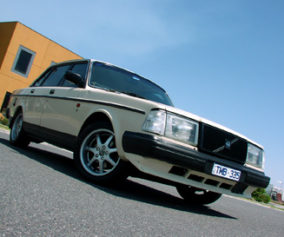
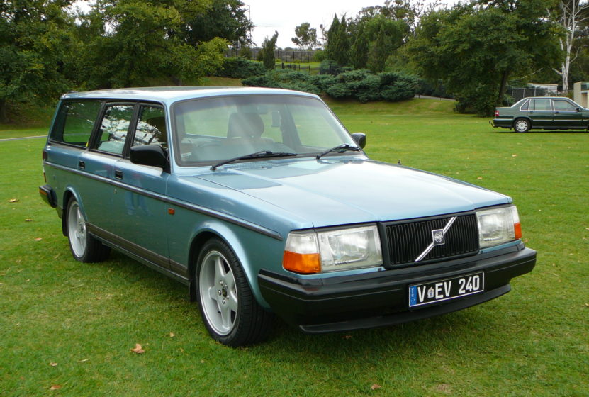
(with no ABS, ESC, airbags, etc.) would reduce complexity and make it easier to gain engineering approval. In the end, we settled on a trusty, and nearly indestructible, Volvo 240 station
wagon. The car is a 1993 240GLE, the last of the 240s built, and in good condition for its age. We kept the car registered during the process so we could test-drive it. We’ve also been told it can be much more difficult to re-register a car as an EV after it’s been off the road for years, while changing an already registered petrol car’s engine type to ‘electric’ is quite simple in Victoria, provided you have the VASS engineer’s certificate. After purchasing the car, we immediately advertised the engine and transmission for sale, so we could start dismantling the car and removing unnecessary parts. If your donor car has a good engine and transmission, it’s good to try and get prospective buyers out to drive the car before you tear it apart. Selling
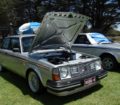
the engine once it’s already been removed can be difficult as the buyer may not trust your assessment of the engine’s condition if they can’t hear it run. Luckily we found a buyer who was willing to help remove the engine and take it away, and he also paid a good price. Sale of the engine and transmission reduced the donor car’s price by nearly 50%! With the engine out, take the opportunity to degrease and power wash the engine bay and tunnel area to remove years of gunk and grime from that dirty fossil-fuelled engine.
First and foremost, we agreed the finished product must be fully approved by a VicRoads-certified VASS engineer and legally registered as an EV in Victoria. We researched the relevant EV standards (NCOP 14 and related VSBs) before we did anything to ensure we wouldn’t break any rules that would prevent us obtaining sign-off. Since we live in an inner Melbourne suburb we settled on a range target of 50-60km per charge, knowing that we’d be able to fall back on public transport or our ‘dinosaur-powered’ car for longer trips. From a performance standpoint, adequate acceleration of seven seconds from 0-60kph, 15 seconds from 0-100kph and a top speed of 100kph would ensure we could keep up with traffic, although faster acceleration would be more fun! We also set some criteria for performance on sloped surfaces, such as going over the Westgate bridge, or driving up a steep car park entry ramp, as it would be extremely embarrassing if the car got stuck during normal driving. Maintaining the original car’s weight distribution was considered ideal for handling and obtaining engineering approval. Finally, since the car could only be driven short distances, we agreed we could live without air conditioning as this would also save weight and reduce complexity.
We made use of a Quality Function Deployment (QFD) tool to build a picture of what we wanted to achieve in terms of our functional requirements. You can tell we’re both engineers, right?
Performance modelling
I investigated ways to evaluate that our project criteria were going to be met as part of my university course. I needed to develop three key models and the total tractive effort equation for our donor vehicle using spreadsheets. The total tractive effort equation describes all the forces acting on the vehicle and includes the rolling resistance, aerodynamic drag, hill climbing force, force required for linear acceleration and the force required to give angular acceleration to the rotating motor. There are many references for this type of analysis, including the book Electric Vehicle Technology Explained by Larmine & Lowry.
The first model to develop was the Wide Open Throttle (WOT) model to evaluate the vehicle acceleration-related criteria. The second was the range model to evaluate the range-related criteria using drive cycles. Finally the Weight Distribution model was used to evaluate vehicle ride, handling and safety-related criteria. As demonstrated in the flow diagram above, you start by selecting the specific battery, motor and controller technology for the EV. Then you combine the information with the vehicle parameters and run the models which gives you a set of design results to evaluate. The range model used several input data sets including the European, New York City, and US EPA drive cycles. The output was then averaged across all drive cycles
to give a range in kilometres to a battery depth of discharge (DOD) of 70%. The first step in the evaluation was to size the battery pack based on our range requirement and estimated vehicle mass. This was done by using the following rule of thumb equation:
• Range (km) = 250 x Battery capacity (kWh)/[Vehicle Mass (kg)] 0.6
Rearranging the equation to solve for battery capacity:
• Battery Capacity = Range x (Vehicle Mass) 0.6 /250 = 50 x (1500) 0.6 /250 ≈ 16kWh
The equation gave us a starting point indicating we would need a minimum of 16kWh total battery capacity to achieve our desired range. The next step was to determine the battery technology and configuration needed to meet the performance targets. We had already decided against using lead-acid batteries due to the weight, instead favouring LiFePO 4 , however, we wanted to confirm our suspicions about lead-acid batteries by doing a comparison between both technologies. The battery pack voltage is limited by our motor (in this case, 172 volts), so we selected 144 volts because of the ease of obtaining standard components such as the charger. Calculations showed we would need a lead-acid battery pack composed of 14 x 12V 100Ah batteries (weighing 478.8kg), compared to a LiFePO 4 pack composed of 45 x 3.2V 130Ah batteries and weighing only 198kg. These two battery configurations were fed into the performance modelling spreadsheet and the results are shown in the table below. Note: we did not take into account Peukert’s law when carrying out the range modelling, nor did we consider the damage inflicted by discharging the lead acid batteries down to 30% state of charge, both of which would have resulted in a shorter battery life and range for the lead acid batteries.
Our prediction was that lead-acid batteries would need to be replaced at least three times over a 10-year period whereas the LiFePO 4 would last 10 years at 70% depth of discharge (DOD). This meant the lifecycle cost of lead-acid was higher than LiFePO 4 even though the initial cost for LiFePO 4 is much higher.
Battery pack configuration
We now had confidence to order our batteries. We selected 45 Sky Energy 130Ah LiFePO 4 batteries. This gave us a total of 18.7kWh based on a nominal battery voltage of 3.2V per battery. Each battery weighs 4.4kg for a total pack weight of 198kg. (Note: Sky Energy has since changed names to China Aviation Lithium Battery Co (CALB)) According to the battery manufacturer, the charge/discharge life is 2000 cycles to 80% DOD or 3000 cycles to 70% DOD. We never intend to go below 70% DOD which means our usable battery capacity
is 13.1kWh. The batteries also have a high discharge rate capability of 4C (520A) continuous and 12C (1520A) pulse, with very low voltage sag. To preserve battery life, we’ve limited the controller current to 3C (390A) for normal driving, with a switchable ‘performance mode’ allowing up to 500A.
Layout and weight
With the donor car purchased and weighed, we started doing the weight calculations. The Volvo came in at about 1390kg with a full tank of petrol, with the weight distribution being 50% front and 50% rear. While we wanted to keep the total post-conversion weight about the same, we knew the car could easily take a bit of extra weight if necessary as the gross vehicle weight is 1750kg.
Early on, we started a spreadsheet and layout sketch so every component removed could be weighed and its approximate fore/aft location noted. From this we estimated what the converted car would weigh and determined the best location for the heaviest components, especially the batteries. We needed to allocate 200kg for our selected batteries. The biggest decision was where to locate them. We could have positioned them under the rear load floor behind the rear axle, but this would have had several issues. First, this meant a large shift of weight to the rear axle and reduction of weight on the front axle, which could have resulted in vehicle dynamics issues. Second, we would have had to cut a large portion of the rear floor structure away and weld in a suitable box to house the batteries (Greg wasn’t keen on cutting up any part of this beloved Volvo!) Third, the batteries would have been in the rear crush zone and more susceptible
to damage in a collision. Another option was to split the battery pack in two, with a portion of the batteries in the motor compartment and a portion below the rear load floor. This would have added complexity as two separate battery enclosures would have to be built, and it would still have required cutting the vehicle’s primary structure for the rear batteries. In the end we decided to remove the rear seat and place the entire battery pack there. We have another five-passenger to transport people. The benefits were numerous. Removing the rear seat saved about 35kg; eliminating three seating positions meant the 65kg allowance per passenger was no longer factored into the GVM calculations; batteries placed between the front and rear axles improved the weight distribution and vehicle dynamics; structural attachments for the battery box were readily available including former seat and seatbelt mounting points; there was no cutting of vehicle structure and it simplified battery management system (BMS) and power cable wiring.
Gearbox and motor mounting
Typically AC motors can spin a lot faster than the larger DC motors, which often means an EV with an AC motor might be able to run with only a single gear ratio to achieve highway speeds. To get reasonable performance with our DC setup, a multi-ratio gearbox was mandatory to avoid drawing too much current when taking off from a stop, yet still allowing highway speeds without over-revving the motor. Some people do choose to go direct drive DC (with only the standard rear differential ratio), but you need about double the batteries and a much larger controller and motor (or dual motors) to get acceleration similar to the same EV with a multi-ratio gearbox as the current draw will be very high when taking off. If you have no gearbox, you also need to electronically switch forward and reverse, which adds complexity (extra contactors, reverse lock-out, etc.) The WarP 9 motor supposedly has a sweet spot at around 3300 rpm where it is most efficient, and the ideal operating range is 2000-4000 rpm, very similar to the original 4-cylinder petrol engine. That being the case, we opted for a standard Volvo four-speed manual gearbox direct-coupled to the motor rear shaft. Some people go with a clutch and some don’t. With a clutch, driving is similar to a petrol car, but given the torque of the motor and typical driving around town being done at 60 to 70kph, most driving can be done in second gear. Shifting to a higher gear is no problem (just let the transmission synchronise momentarily between gear changes) and shifting down can be done easily when you come to the next set of lights. No clutch also means no slippage, one less thing to replace and less likelihood of accidentally over-revving the motor while engaging the clutch. With the decision made to go clutchless, we procured a good used manual transmission then started designing the motor mounts, motor coupling and motor-to-transmission adaptor plates. For the first ‘prototype’ installation, Greg made a mock-up of the motor using some leftover tin and MDF. This was much lighter and easier to work with than the heavy electric motor and confirmed that the motor would easily clear the steering and suspension components. Most people have a machine shop fabricate an aluminium plate to join the motor to the transmission’s bellhousing, but we have access to a drill press and various other tools, so we decided to make it ourselves. Capral Aluminium centres provide cut-to-order material at reasonable prices, so we started with a 16mm thick aluminium plate. The dimensions from the electric motor and the transmission bellhousing were carefully transcribed onto the aluminium plate and, after drilling the holes and bolting it all together, it looked pretty good. In addition to the 16mm plate we bought three purpose-built 1⁄2-inch thick motor spacer plates from an EV parts supplier in the USA. This positioned the motor appropriately to the transmission input shaft and Greg designed a steel coupling to join the motor shaft to the transmission. We had a machine shop turn up the coupling and also modify the centre splined section of the clutch disc, which is bolted rigidly to the coupling. With the coupling and adaptor plate complete, Wayne hooked the motor up to a 12 volt battery so we could test the setup for alignment and balance. It was all good, with no vibration!
Another challenge was how to mount the motor to the car’s front crossmember. Obviously you need to design the mounting structure to ensure the transmission and driveshaft(s) will be in the correct position and alignment to avoid nasty surprises like drivetrain vibrations and things banging into the body. We bolted another aluminium plate to the front of the motor and put fore/
aft bridging tubes from the front plate to the rear adaptor plate. These tubes then bolt to the car’s rubber engine mounts and everything is attached as it was meant to be from the factory. Having plates at the front and rear of the motor allowed us to create a flat mounting base (and heatsink) on top for the controller and front contactor enclosure. Once the motor, adapter plates and mounting structure were completed, a lick of paint was applied and the whole thing assembled and hoisted into position in the car’s body. I again tested the balance of the motor and coupling, and it seemed OK, so no need to remove and fiddle with the mounting position again—hooray!
The battery box
While waiting for the batteries to arrive, we made several mock-ups of the proposed battery box shapes using leftover cardboard boxes. The lithium batteries have top terminals and must be held tightly to avoid expansion when they charge or discharge. We had to decide whether we’d have three rows of 15 batteries, five rows of nine batteries, or another combination. In the end it came down to ensuring we would still have full front seat travel while also configuring the batteries to eliminate bridging wires within the battery box enclosure, as well as having the positive and negative wires come out on the same end of the battery box. Greg used Google SketchUp (free CAD software) to draw up a design for the battery enclosure. The batteries have 16mm recesses running up each side, so we used this feature to key into 16mm solid aluminium bars running the width of the battery box. This prevents the batteries from being able to come out
during a roll-over, and also neatly locates them in the enclosure. The walls and base of the battery box are made from 6mm aluminium and the entire box is a bolted design to allow easy disassembly if required in future. The box is supported by a 25mm x 50mm steel RHS frame and the assembly is attached at 11 points to the vehicle’s body structure. Other than drilling
several bolt holes, no cutting of the car’s structure was required. The regulations state that the batteries must be able to withstand a 20g (20 times the battery weight) forward crash deceleration as well as 15g side, 10g rear and 10g rollover. Rough calculations showed that our attachment scheme was well-designed to cope with these loads with a large factor of safety.
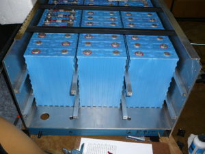
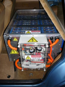
Building the battery box was a major undertaking—probably the most difficult part of the conversion. Many hours were spent in the garage during an extended Christmas holiday break from school and work. The hard work paid off and by the end of the holidays we installed the box and loaded the batteries into it. Loading the batteries was no small task as the keyed feature required each battery to be slid into position from one end of the battery box. Everything fit very tightly so there’s no vibration or relative movement between adjacent batteries. The finished product looks somewhat akin to a bank vault and is obviously over designed! To hide and protect the battery box but still allow monitoring of the BMS LED indicators, we fitted a lockable hinged plywood cover that is trimmed in the same carpet as the rest of the load floor. Underneath the plywood cover there’s a clear acrylic cover that enables viewing of the LEDs but prevents any access to live electrical terminals, as required by standards. This cover can be removed with tools if required to check individual battery voltage. Battery cables and electrical enclosures The rear electrical enclosure is mounted on the left side of the battery box, enabling the shortest possible cable routing from the batteries to the fuses. The box contains a Tyco Kilovac 500A, 320VDC contactor, two 500A, 300VDC Ferraz/ Shawmut fuses and the TBS battery gauge shunt and voltage pre-scaler. The main battery cables are double-insulated 95mm2 copper. We chose this up-sized cable because the small increase in weight was a small price to pay for improved conductivity (less resistance and so less wasted heat). The cables run from the rear electrical box out through grommets in the floor pan and along the transmission tunnel (where the original fuel lines ran) to the motor compartment and are protected by rigid orange conduit. We found the conduit could be bent slightly using a heat gun to neatly follow the contour of the tunnel. In front, a sealed electrical enclosure mounted on the top of the motor houses the Zilla controller, as well as another Tyco contactor and fuse for the ancillary HV devices. Another enclosure houses the brain for the Zilla, known as the ‘Hairball’. There is also a small enclosure containing fuses for the heater and DC/DC converter. Charging and the BMS Because each battery varies slightly in capacity due to manufacturing tolerances, lithium battery packs require a battery management system to ensure that all the batteries maintain a balanced state of charge. We selected the locally made (Perth) EV Power system, which uses a BMS module on each battery which is linked via a simple single-wire loop to a central control module. The cell modules continuously monitor each battery’s voltage and can sound an alarm if any one battery goes out of the specified range. During charging, each module can shunt current across any cell that achieves a specified voltage to prevent that battery from overcharging. The BMS controller can also turn off the charger or warn the driver if it detects a fault condition (such as over- or under-voltage or a BMS module fault). For charging, we used the car’s original
fuel filler location and fitted a 15 amp water-resistant caravan charge port. We plan to replace this with an SAE J1772 standard EV charging port as it would be nice to be able to charge at commercial EV charging stations once they become available. The Zivan charger can draw up to 12.5 amps at 240 volts, so we had to have a 15 amp power point installed in our garage at home. On the charge port door, we fitted a microswitch that’s interlocked with the controller to ensure the car can’t be accidentally driven away while plugged in.
Brake vacuum
Because there’s no petrol engine to develop vacuum for the power brake booster, EVs require a separate vacuum pump. We used a Bosch UP28 auxiliary vacuum pump, which is commonly found on newer direct-injection and turbocharged cars. The pump is connected to a large vacuum reservoir and I built an Arduino based controller that senses vacuum using a manifold pressure sensor to turn the pump on and off as required. The pump can just be heard from inside the car if you’re sitting at a stand-still and is inaudible once the car is moving. With the vacuum tank, the pump only comes on after several stops and it only takes a few seconds to get back to full vacuum. To monitor the vacuum system we fitted a VDO vacuum gauge in one of
the spare instrument panel binnacles and an adjacent LED illuminates if the brake vacuum drops below the lower set point to warn the driver of a malfunction in the vacuum system.
Heating
The ADR (Australian Design Rules) requirements state you must have an effective windscreen defogging system, so we kept the car’s heater fan and ducting. We removed the air conditioning condenser and heater core from the HVAC (heating, ventilation and air conditioning) box and replaced these with two 240 volt ceramic heater cores salvaged from new household space heaters. Greg fitted the cores and associated shrouding onto a metal plate which was then slid into place in the HVAC box. While I did the HV wiring for the heaters using optically-coupled
relays, Greg fitted a couple of microswitches to the car’s original heater control lever to provide low and high heat levels. All this was wired to ensure the heater elements can’t be turned on unless the fan is switched on and an LED by the fan switch indicates when the heater is on. Heat output is decent, although nowhere near as hot as the Volvo’s original heater, which was obviously designed for the coldest of Scandinavian winters! We also fitted seat heaters to take the chill off when the heater isn’t required.
DC-DC converter
Another important issue to consider when converting a car to an EV is how to run the car’s original 12 volt systems. While there are several options, we retained the car’s 12 volt battery and fitted a Meanwell PB-600 DC-DC converter that runs off the main battery pack to keep the battery charged. Because the converter isn’t waterproof, we mounted it in the glovebox where it could conveniently feed off the nearby HV fuse panel. It’s amazing how many EVs you see with chargers, DC-DC converters and controllers that are mounted in the engine compartment yet have no waterproofing whatsoever. Just don’t ever drive in rain or wash your car and you’ll be fine (remember you can only let the smoke out once!). The only issue with having the DC-DC mounted in the car is you can hear the cooling fan running when you’re not moving. The fan speed varies with the load, so you can only really hear it if you have the headlights on or are using other 12 volt accessories. If done again, we’d probably mount the converter in the rear of the car under the load floor where you wouldn’t be able to hear the fan at all. Water pump and radiator The Zilla controller must be water cooled. We’ve read that it’s not mandatory, but we found out the hard way (when the water pump wasn’t running on our first big drive to VicRoads for registration change-over) that the controller quickly gets hot and starts limiting the current to protect itself. We fitted a Delphi high-performance gaming PC 12 volt water cooling pump feeding a small radiator mounted below the front bumper. Other than the early incident (which was corrected by rewiring the pump so power is supplied directly from the fuse panel) the setup
works great and the controller has never gone over temperature. The pump is inaudible from inside the car. Even with the bonnet open and the pump running, all you can hear is a gentle trickling as the water returns to the expansion tank.
Battery gauge
To monitor the battery pack state of charge, voltage, instantaneous current and temperature, we installed a TBS E-Xpert Pro battery gauge. The gauge works with a precision shunt to measure current and integrates the current versus time to calculate the amp-hours used during driving. The battery pack has a rated capacity of 130 amp-hours at full charge and, as you drive, the TBS gauge displays the state of charge (SOC) remaining. To improve the life of the batteries, it is recommended to never discharge them below a 20-30% SOC, so we have the gauge set up to provide a visual warning when the SOC drops to 50%. In Greg’s 23km daily commute from Williamstown over the Westgate Bridge to Port Melbourne and return, the battery still has about 70-75% capacity remaining at the end of the day. To charge the battery back to full capacity for the next day’s use takes just over three hours.
Suspension and steering
Because we took approximately 20kg off the front axle and added 90kg to the rear axle, the car was sitting a little lower in the back and too high in the front. Greg obtained a set of lower front springs from a fellow Volvo Club member and swapped those in while fitting new Bilstein HD shock absorbers. We also fitted heavier stabiliser bars to reduce any body lean in corners. The ride is now level and nicely firm and the car handles roundabouts with ease. We procured a manual steering rack from an earlier Volvo of the same model which was a direct bolt-in replacement. This was necessitated by the removal of the original petrol engine’s belt-driven power steering pump. Some people fit an electro-hydraulic power steering pump to retain power steering, but we didn’t really think it was necessary given the reduced weight on the front axle. The manual steering is a bit heavy when parking, but not really a problem.
Aerodynamics
One unfinished part of the project is aerodynamic treatment. Given most of our driving is done at 60 to 80kph, it hasn’t been a priority. The one thing we do plan to tackle is putting a panel behind the rear axle to close out the large open cavity where the petrol tank and rear muffler used to sit. Even if it doesn’t do much for aerodynamics, it will improve the aesthetics of the area that currently looks like there’s something missing. We’ll also put a clear cover over the grille to deflect air up and over the bonnet and possibly add a close-out panel on the tunnel under the transmission. Another useful aerodynamic aid might be a rubber lip spoiler on the bottom of the existing lower front bumper air dam.
Driving the eVolvo
The first thing you notice is how quiet the car is with no engine. When you’re stopped at traffic lights, you hear other people’s cars idling away, wasting petrol and you can even hear birds singing! At speed, you can hear a slight whine from the motor and transmission—it sounds very futuristic. Driving around town has some similarities to driving an automatic. There’s no clutch pedal and you don’t have to do anything when you come to a stop. You start off in second gear and just stay there for most urban commuting at speeds of up to 70kph. For higher speeds,
you simply let off the accelerator and ease the gear lever into a higher gear, letting the transmission’s synchros do the work (third gear for 70-100kph and fourth gear for 100kph+). There’s no real need to ’down-shift’ due to the torque of the motor, so you usually just wait until the next traffic light stop to shift into a lower gear if necessary, as it can be tricky to down-shift on the fly with no clutch—but it can be done by matching the motor revs to the vehicle’s speed. The silence is so enjoyable that Greg hasn’t even been using the radio on his commute to work.
In terms of the power and acceleration, it feels better than the original car. It’s pretty quick off the mark as the electric motor has full torque from zero RPM. Going up the Westgate Bridge is no problem at all and you can coast down the other side using no throttle. The car will easily cruise in fourth gear at 100kph and still has plenty of pull at that speed. Top speed is likely to be over 130kph but we don’t plan to get a speeding fine to prove it! The range in normal driving compares well to the initial calculations, with 60km to 70km achievable on a single charge, although we rarely drive more than 40km between charges.
Economy and financial
To measure the charging electricity, we purchased a 15A PowerMate energy meter and we diligently record all energy used to charge the car. Based on the first 1500km of driving, we’re using about 250 watt-hours per kilometre. This equates to 4km of driving for every kilowatt-hour of electricity (about five cents per kilometre using GreenPower), which isn’t bad compared to the cost of petrol. Driving about 6000km per year, the savings using electricity versus petrol is about $750 per year at today’s prices. Therefore the pay-back period on our investment will
be measured in decades, not years, but that’s not the point! At current exchange rates and with the cost of batteries coming down, you could probably duplicate this conversion for $20,000 to $25,000, assuming you did all the work yourself. It could be done much cheaper with lower-quality components, but we chose to use top-of- the-line hardware. With the cost of petrol likely to rise as oil becomes more scarce, it looks like the electric car could be up for a bright future.
Republiched from Renew magazine with permission from Greg Sievert, Volvo Club member and Volvo enthusiast